Top Previous Year Questions - Semiconductors
Question
Identify the operation performed by the circuit given below :
JEE Main 2020 (04 Sep Shift 2)
Options
- A: NAND
- B: OR
- C: AND
- D: NOT
Explaination
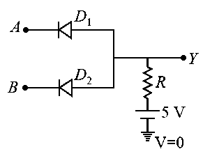
Question
Both the diodes used in the circuit shown are assumed to be ideal and have negligible resistance when these are forward biased. Built in potential in each diode is . For the input voltages shown in the figure, the voltage (in Volts) at point A is ________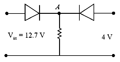
JEE Main 2020 (09 Jan Shift 1)
Enter your answer
Explaination
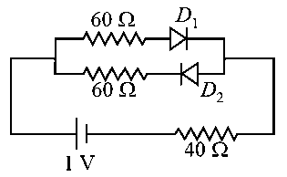
Question
The current in the network is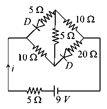
JEE Main 2020 (09 Jan Shift 2)
Options
- A:
- B:
- C:
- D:
Explaination
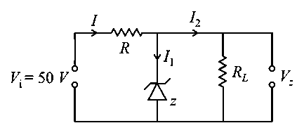
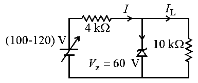
Question
In the circuit shown below, is working as a regulated voltage source. When is used as an input, the power dissipated (in ) in each diode is (Considering both zener diodes are identical) 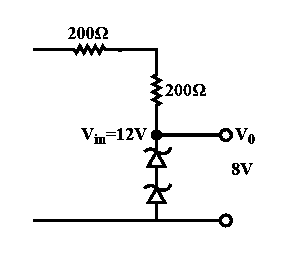
JEE Main 2020 (09 Jan Shift 2)
Enter your answer
Explaination
Question
For extrinsic semiconductors; when doping level is increased;
JEE Main 2021 (25 Feb Shift 2)
Options
- A: Fermi-level of and - type semiconductors will not be affected.
- B: Fermi-level of -type semiconductor will go upward and Fermi-level of -type semiconductors will go downward.
- C: Fermi-level of both p-type and n-type semiconductors will go upward for and downward for where is Fermi temperature.
- D: Fermi-level of - type semiconductors will go downward and Fermi-level of - type semiconductor will go upward.
Explaination
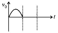
Question
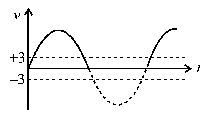
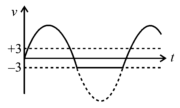
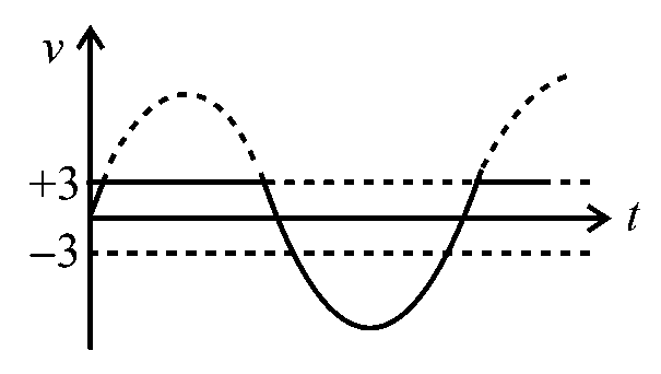
Choose the correct waveform that can represent the voltage across of the following circuit, assuming the diode is ideal one: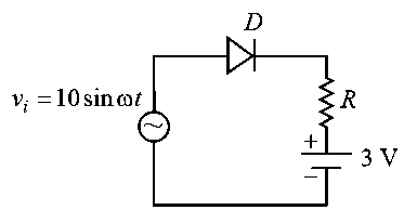
JEE Main 2021 (31 Aug Shift 1)
Options
-
A:
-
B:
-
C:
-
D:
Explaination
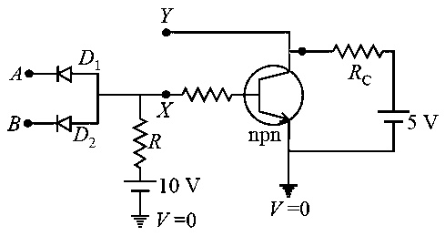
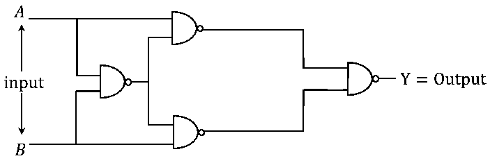
Question
In the logic circuit shown in the figure, if input and are to respectively, the output at would be . The value of is _________.
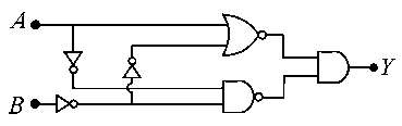
JEE Main 2021 (16 Mar Shift 1)
Enter your answer
Explaination
Question
For the forward biased diode characteristics shown in the figure, the dynamic resistance at will be ________
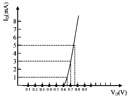
JEE Main 2021 (20 Jul Shift 2)
Enter your answer
Explaination
Question
In a given circuit diagram, a zener diode along with a series resistance is connected across a power supply. The minimum value of the resistance required, if the maximum zener current is will be
JEE Main 2021 (22 Jul Shift 1)
Enter your answer
Explaination
Question
In the circuit, the logical value of or when potential at or is and the logical value of or when potential at or is .
The truth table of the given circuit will be :
JEE Main 2022 (25 Jul Shift 1)
Options
- A:
- B:
- C:
- D:
Explaination
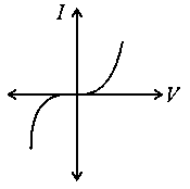
Question
Identify the solar cell characteristics from the following options :
JEE Main 2022 (28 Jul Shift 1)
Options
-
A:
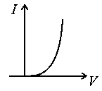
-
B:
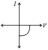
-
C:

-
D:
Explaination
Question
In the following circuit, the correct relation between output and inputs and will be
JEE Main 2022 (28 Jun Shift 1)
Options
- A:
- B:
- C:
- D:
Explaination
Question
In the given circuit the input voltage is shown in figure. The cut-in voltage of junction diode ( or ) is . Which of the following output voltage waveform across the diode is correct?
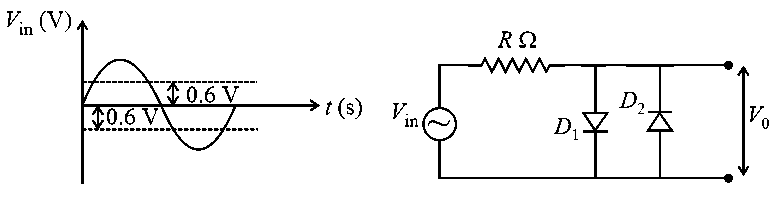
JEE Main 2022 (28 Jun Shift 2)
Options
-
A:
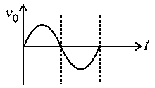
-
B:
-
C:
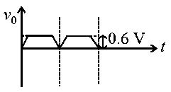
-
D:
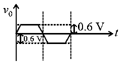
Explaination
Question
In the circuit shown below, maximum Zener diode current will be _____ .
JEE Main 2022 (26 Jul Shift 1)
Enter your answer
Explaination
Question
The cut-off voltage of the diodes (shown in figure) in forward bias is . The current through the resister of is _____ .
JEE Main 2022 (27 Jun Shift 2)
Enter your answer
Explaination
Question
Given below are two statements : one is labelled as Assertion A and the other is labelled as Reason R
Assertion A: Photodiodes are used in forward bias usually for measuring the light intensity.
Reason R: For a junction diode, at applied voltage the current in the forward bias is more than the current in the reverse bias for where is the threshold voltage and is the breakdown voltage.
In the light of the above statements, choose the correct answer from the options given below
JEE Main 2023 (25 Jan Shift 1)
Options
- A: Both A and R are true and R is correct explanation A
- B: Both A and R are true but R is NOT the correct explanation A
- C: A is false but R is true
- D: A is true but R is false
Explaination
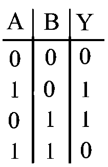
Question
The output for the inputs and of circuit is given by
Truth table of the shown circuit is :
JEE Main 2023 (30 Jan Shift 2)
Options
- A:
- B:
- C:
- D:
Explaination
Question
A zener diode of power rating is to be used as voltage regulator. If the zener diode has a breakdown of and it has to regulate voltage fluctuating between and The value of resistance for safe operation of diode will be
JEE Main 2023 (10 Apr Shift 1)
Options
- A:
- B:
- C:
- D:
Explaination
Question
Choose the correct statement about Zener diode:
JEE Main 2023 (01 Feb Shift 2)
Options
- A: It works as a voltage regulator in reverse bias and behaves like simple p-n junction diode in forward bias
- B: It works as a voltage regulator in both forward and reverse bias
- C: It works a voltage regulator only in forward bias
- D: It works as a voltage regulator in forward bias and behaves like simple p-n junction diode in reverse bias
Explaination
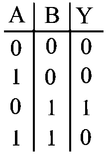
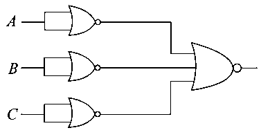
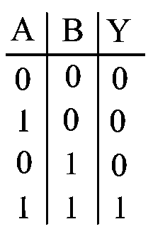
Question
In the truth table of the above circuit the value of $\mathrm{X}$ and $\mathrm{Y}$ are :
JEE Main 2024 (09 Apr Shift 2)
Options
- A: 0,0
- B: 1,1
- C: 1,0
- D: 0,1
Explaination
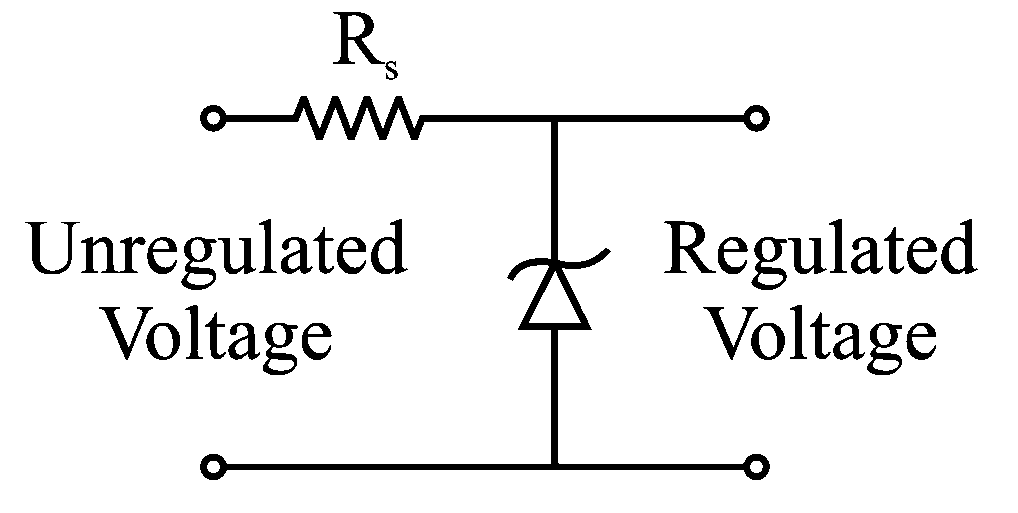
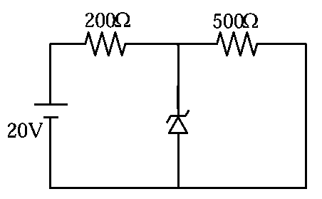
Question
In the given circuit, the breakdown voltage of the Zener diode is . What is the value of ?
JEE Main 2024 (29 Jan Shift 1)
Options
- A:
- B:
- C:
- D:
Explaination
Question
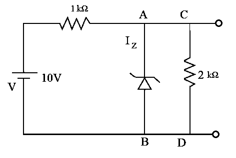
A Zener diode of breakdown voltage is used as a voltage regulator as shown in the figure. The current through the Zener diode is
JEE Main 2024 (30 Jan Shift 1)
Options
- A:
- B:
- C:
- D:
Explaination
Question
In the given circuit if the power rating of Zener diode is , the value of series resistance to regulate the input unregulated supply is:
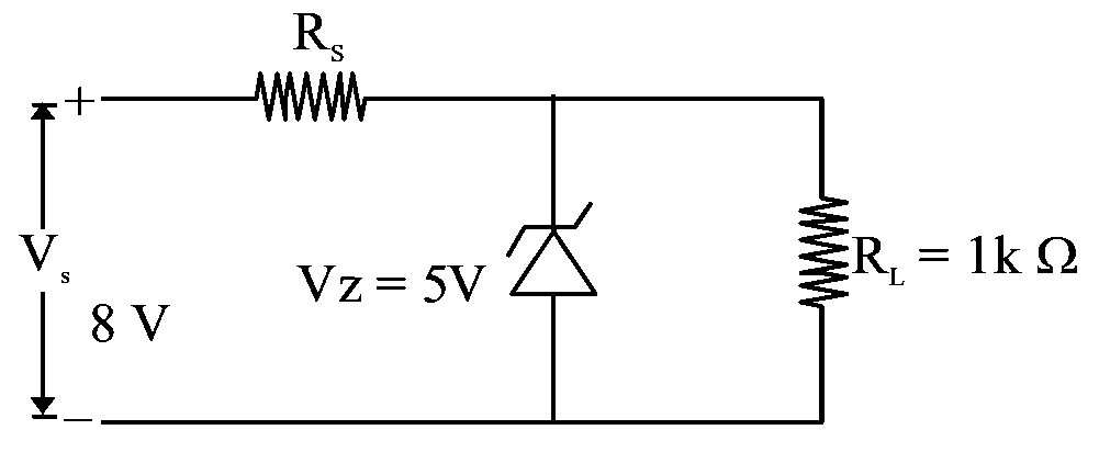
JEE Main 2024 (01 Feb Shift 1)
Options
- A:
- B:
- C:
- D:
Explaination
Question
The output of the given circuit diagram is
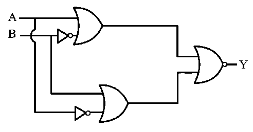
JEE Main 2024 (31 Jan Shift 2)
Options
-
A:
-
B:
-
C:
-
D: